Kenwood TH-D72 APRS Checklist

The following checklist was created from a YouTube video “Basic setup for APRS operations with the Kenwood D72” by Don Arnold.  I really recommend you view this video.  The reason I wrote this list is because there are about 10 APRS setup steps.  I seldom use this radio and when I do, I want a quick check list to ensure the APRS is working.

  • * Turn Internal GPS On
    • * “F” Key = 1 “Int. GPS” (note that “F” key changes APRS menu items.)
    • * Turn ON.
    • * Confirm that “iGPS” appears upper right of screen.
  • * Turn Battery Saver OFF
    • * Press MENU
    • * Select RADIO = Menu 1
    • * Go to MENU = 110 = “Batt. Saver”
    • * Select OFF.
  • * APO OFF (automatic power off)
    • * Press MENU
    • * Select RADIO = Menu 1
    • * Go to MENU = 111 = “APO”
    • * Select OFF
  • * Set the DATE
    • * Press MENU
    • * Select RADIO = Menu 1
    • * Go to MENU = 194
    • * Enter correct date.
  • * Set the Time
    • * Press MENU
    • * Select RADIO = Menu 1
    • * Go to MENU = 195
    • * Enter the correct time.
  • * Set the UTC
    • * Set the UTC
    • * Select RADIO = Menu 1
    • * Go to MENU = 196 = Auxiliary, Time Zone, UTC
    • * Set to -7 Daylight Savings (for California)
    • * Set to -8 Standard Time (for California)
  • * Set the int. GPS
    • * Select GPS = Menu 2
    • * Go to MENU = 201 = Int. GPS = Operating Mode
    • * Sub menu = Battery Saver = OFF
  • * APRS Setup – BASIC SET
    • * Select APRS = Menu 3
    • * Go to MENU = 300 = Call Sign
    • * Go to sub menu “My Callsign”.
    • * Enter your call sign.
  • * EXIT OUT OF MENU
    • * Enter 144.390 = APRS Frequency for the USA
  • * Press TNC button. (this opens the TNC)
    • * Look at screen. You should see “APRS12”.

Now Lets confirm that the radio is “seeing” the GPS satellites and the APRS circuits are working properly:

  • * OPTIONS
    • * Press POS key which will show degrees, minutes seconds. Make sure the small circles just to the right of each is blinking on and off.
    • * You can press the radio joy stick to see your Altitude.
    • * Target Point is another display. Target Point is recorded in the HT.  Up to 5 points can be stored.  (Its accuracy is not good enough for Geocaching.)
    • * You can view the log memory used.
    • * You can view satellites.
  • Beacon
    • * If you have manual beacon set, press “BCON” key to send your position.

Sun Storm To Hit Earth August 4, 2017

Space Weather News for August 3, 2017
http://spaceweather.com
https://www.facebook.com/spaceweatherdotcom

GEOMAGNETIC STORM WATCH: NOAA forecasters say there is an 80% chance of polar geomagnetic storms on Aug. 4th when a solar wind stream is expected to buffet Earth’s magnetic field. The wind is flowing from a canyon-shaped hole in the sun’s atmosphere, so wide that it is almost bisecting the solar disk. Storm levels could reach G2-category (moderately strong) during the late hours of Aug. 4th, subsiding to G1-category (minor) on Aug. 5th. Visit Spaceweather.com for more information and updates.

Boost Your HT Performance With A Rat Tail

A rat tail is a wire attached in some way to the ground of your HT.  It effectively adds the missing part for your antenna system.  This missing part is the ground wire that matches the length of your antenna length.  In normal, every day activity, you really do not need this device.  But, if you are going to travel into an area where repeater coverage is iffy, you might consider taking this simple device along with you.  You can easily make this device yourself and the cost is cheap.  I calculate the wire and connector is less than $1.

Recommended Internet Information:  http://www.hamuniverse.com/htantennamod.html

Construction Materials:

Connector: Insulated Ring 22-18 Guage. 1/4 inch, Vinyl, package of 100 $4.95

Wire: Beldon 8890. 10 feet $9.90 I was able to make 6 rat tails from 10 feet when I cut each length 20 inches.

Vendor: Orvac Electronics, Fullerton, Calif.

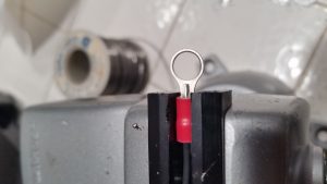
Image shows a small vise holding the O connector and a wire that has been tinned with solder threaded into the back end of the connect with just enough exposed wire ready to be soldered.
Connector and wire ready to be soldered.
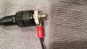
The antenna connector is shown in a close up with the rat tail O connector with wire slid into the ground of the antenna.
Rat Tail connector shown gripping antenna ground.  This connector is for a Baofeng HT.
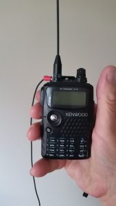
The image shows a person holding a HT radio and comming off the antenna connection base is the rat tail wire ground.
Rat tail ground is attached to a Kenwood TH-F6 radio.

After constructing my first rat tail I decided to test its performance.

Test 1: I walk with another ham radio operator each weekend morning. The other operator lives about a mile away and we start walking toward one another and join up at Tri-City Park. I told him I wanted to test the rat tail the night before. The next day as we walk out of our houses and try calling one another, he reported that my signal was improved. Normally when we start walking from our front doors, the audio is scratchy.

Test 2: August 1, 2017 I tried to find a repeater that would respond with the rat tail but not when it was removed. I finally found Sunset Ridge, 145.440, using low power. When the rat tail was removed from the HT the repeater would not respond. When I put the rat tail in place, the repeater did respond. This second test proved that the rat tail is a definite improvement.

Note: This connect

Caution:  After about a week and a half wearing this rat tail on my HT, I noticed that the wire coming from the connector seemed to fray, a bit, due to the constant bending.  I need to solve this problem.